1. Core Energy Block (Cells & Modules)
Cell Chemistry and Intrinsic Safety
The choice of cathode chemistry—LFP (LiFePO4) or NMC—strongly dictates the fundamental safety and thermal characteristics of the battery cells. LFP uses a robust olivine (Fe-P-O) lattice that retains structural integrity even when deeply discharged; it generates less heat under abuse and is far more thermally stable. For example, LFP’s strong P-O bonds make its cathode intrinsically less prone to oxygen release above ~300°C, giving it a wedge in thermal stability and safety.
In fact, fire-propagation tests show that a short through an LFP cell produces heat and runaway significantly more slowly than NMC: the thermal runaway reaction in an NMC-811 cell proceeds roughly nine times faster (five times faster overall) than in a comparable LFP cell. In practical pack design, this means LFP-based packs require fewer engineered safeguards for thermal events (e.g., less venting/hot-spot management), whereas NMC packs demand stricter safety measures, such as more robust cell spacing, thermal barriers, or suppression materials to inhibit rapid propagation.
By contrast, NMC cells (with Ni-Mn-Co layered oxides) have higher nominal voltage (~3.7V) and energy density but are chemically more volatile at high states of charge or temperature. Cobalt and nickel can catalyze exothermic decomposition of the electrolyte at elevated 70–90°C and can produce large quantities of oxygen or reactive products, significantly raising the risk of thermal runaway. Numerous studies note that LFP’s elimination of cobalt yields far greater abuse tolerance: leading EV makers now state LFP’s advantage in “intrinsic safety” vs. NMC/NCA chemistries. In summary, LFP cells give an inherently safer core module, whereas NMC cells pack more energy but at the cost of higher thermal risk and stringent safety controls.
Cycle Life and High-Temperature Endurance
LFP cells typically exhibit dramatically longer cycle-life performance under comparable conditions. Industry data suggest LFP can endure on the order of 3,000–5,000 full cycles (to ~80% depth) while retaining ~80% capacity, whereas NMC cells generally fall in the 1,000–2,000 cycle range. This longevity is aided by LFP’s stable crystal lattice, which resists the structural changes and cathode dissolution that afflict layered oxides during cycling.
Importantly, these advantages hold in high-temperature environments: LFP’s thermal robustness slows down capacity fade mechanisms. (At elevated ambient, LFP cells do still suffer iron-ion dissolution into the electrolyte, which leads to SEI buildup and impedance rise, but designs with protective coatings or electrolytes can mitigate this.) By contrast, nickel-rich NMC cells experience accelerated degradation at hot climates – cobalt reduction and manganese dissolution become more pronounced, and the electrolyte breaks down more readily – so their cycle life is even more sensitive to ambient heat.
In effect, LFP packs promise much higher TCO due to longevity, while NMC packs will degrade faster if operated continuously in 45–50 °C conditions.
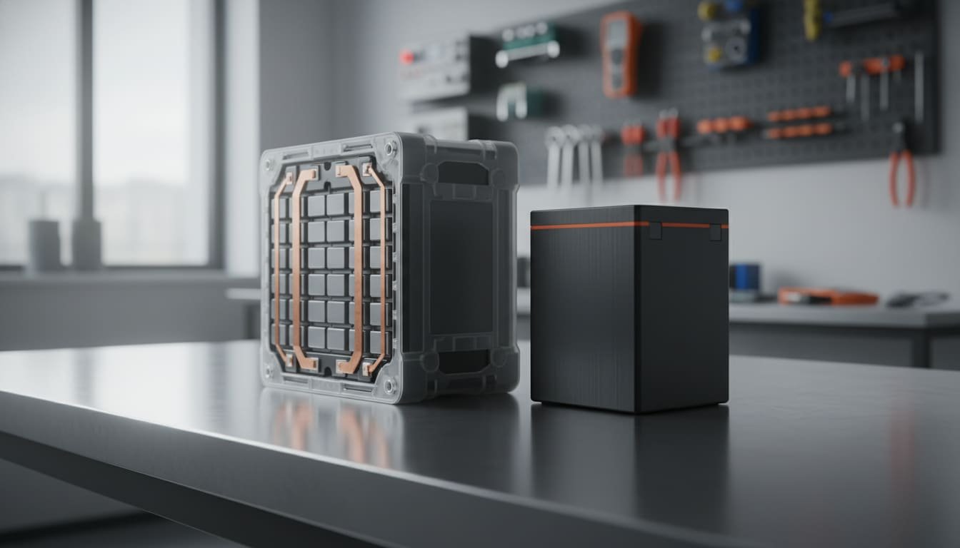
Energy Density and Module Configuration
The higher-voltage NMC chemistry yields about 150–250 Wh/kg cell-specific energy versus roughly 120–160 Wh/kg for LFP. In a fixed 48 V system, this means that LFP packs must use more cells in series (and often in parallel) to reach the same total capacity. For example, a 48 V LFP module might be ~15 S (15 cells in series) whereas an NMC pack might be ~13 S to hit 48 V nominal. Achieving equal pack energy thus typically requires ~20–30% more LFP cells, which inflates the size and weight of the core energy block unless compensated by advanced integration. Indeed, analyses show that while single-cell LFP energy is much lower, careful cell-to-pack design (such as blade cells or cell-as-structure concepts) can shrink the volumetric gap: one study found that optimized LFP integration yields packs that are only ~16% heavier gravimetrically and nearly equal volumetrically to NMC designs.
From a module-design viewpoint, this trade-off manifests in several ways. More cells (and therefore more terminals) mean longer busbars and more interconnects. LFP packs therefore tend to have more complex busbar layouts and greater overall conductor length for a given capacity; however each LFP cell might see a slightly lower per-cell current (since capacity is spread over more cells). NMC packs, with fewer but higher-energy cells, can achieve high capacity in a smaller volume. This is advantageous where space or weight is tight (e.g. EV traction), but in 48 V stationary packs it mainly translates to a lighter battery. On the other hand, the denser NMC chemistry intensifies heat per volume and requires larger fuse/contact sizes per cell if currents are comparable. In sum, LFP-based modules are larger and heavier but simpler thermally, whereas NMC modules are more compact but require larger cooling infrastructure and safety margins due to their higher energy density.
Series/Parallel Configuration and Cell Spacing
In practical terms, LFP packs in a 48 V architecture might choose e.g. 15 S × 4 P (for a given Ah capacity), whereas NMC might be 13 S × 5 P for similar energy (numbers illustrative). The extra series count in LFP affects BMS balancing (more cells to monitor) but also spreads voltage rise per cell more evenly, potentially easing insulation stress. Module gaps and spacings are also influenced: LFP’s lower heat output allows tighter cell-to-cell spacing within modules. By contrast, NMC modules often deliberately incorporate spacing or thermal interface material between cells to allow airflow or heat conduction – essentially enforcing fatter modules. These mechanical layouts then drive busbar sizing: the pack current ultimately dictates copper cross-section, but the number of cells in series/parallel affects busbar lengths and busbar heat dissipation. Overall, one sees denser North-South stacking and integrated design in NMC modules (to minimize volume) versus more spacious, over-dimensioned modules in LFP packs (capitalizing on heat tolerance).
2. Mechanical Structure & Thermal System (Housing & Cooling)
Cooling Strategy – LFP vs. NMC
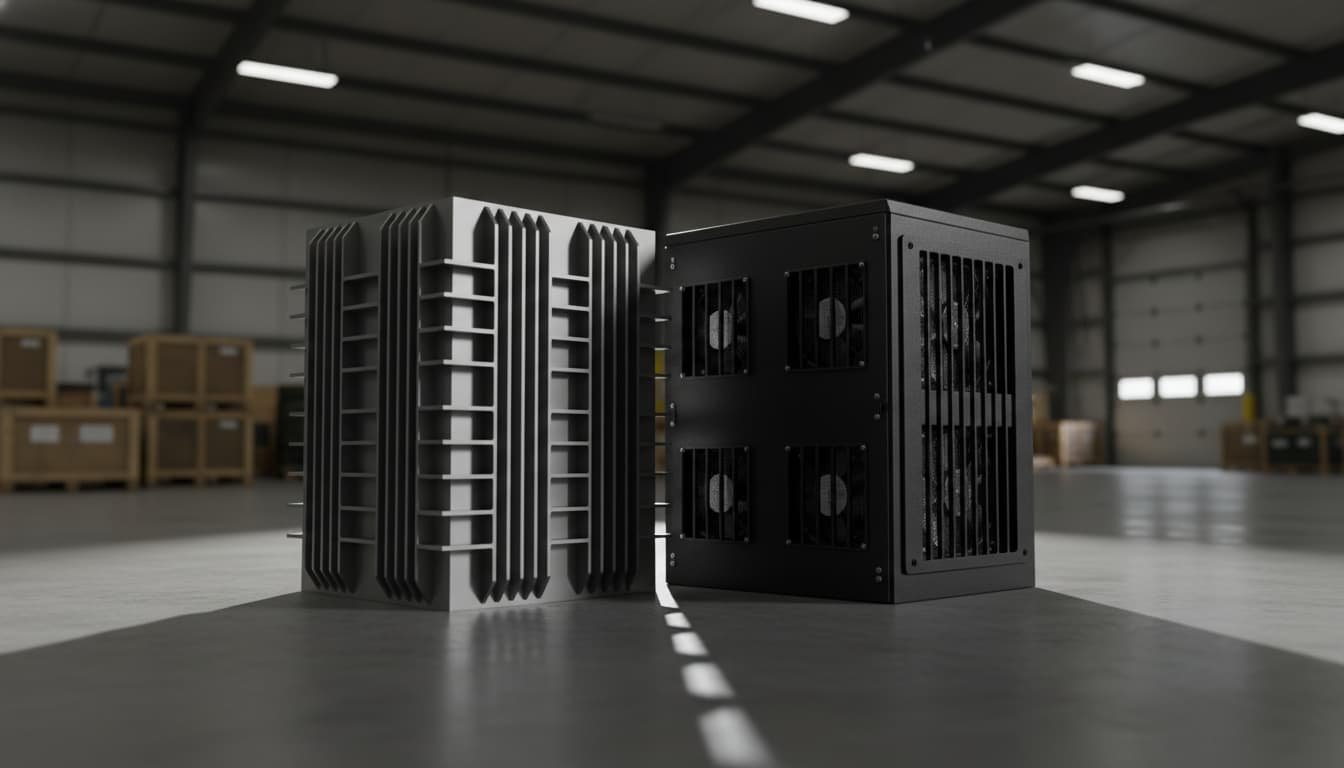
The core differential in heat management is that LFP cells typically produce far less excess heat during charge/discharge than NMC cells of comparable size. LFP’s internal resistance and exothermic kinetics are lower, and its reactions are less violent at high SOC. In practice, this allows a 48 V LFP pack to rely heavily on passive cooling: for example, cells can be arranged with pressure plates or aluminum heat-sink plates that conduct heat away to the enclosure fins.
Many LFP racks use finned aluminum housings or even an open-rack design (with appropriate guards) because the cells rarely exceed safe temperatures in normal operation, even in hot climates. By contrast, NMC cells in a compact pack can quickly generate hotspots; packs usually include active cooling (forced air or liquid/glycol loops). Fans or blower systems are common to draw air through the NMC modules, especially under sustained high load or charging, to keep cell temperatures from creeping above approximately 50–60 °C. In short, LFP favors blower-less, conduction-cooled designs, whereas NMC often necessitates blowers or coolant circuits, adding components that can fail in dusty conditions.
Housing Materials and Design
Given the operating environment (Middle East/Africa), the housing must resist dust, sand, and extreme temperatures. Battery enclosures are thus typically made of robust metal – often powder-coated steel or anodized aluminum – to withstand abrasion and to serve as a heat sink and EMI shield. Aluminum is popular for its combination of light weight and high thermal conductivity (helpful for passive cooling of LFP packs), whereas steel chassis may be used for very high-density NMC packs for strength and fire protection. All enclosures are sealed to a high IP rating. At minimum, an IP54–IP65 rating is required for desert use (to stop fine dust ingress), but many designs target IP67 (dust-tight with ventilation breather or sealed connectors) so that brief rain or wash-downs are tolerated. Indeed, IP67 keyboards, enclosures and glands are standard for outdoor telecom/mobile battery shelters.
Ingress Protection (Dust/Water)
A sealed IP67 enclosure prevents sandbox conditions on the electronics and cells. As a rule, higher IP ratings add mechanical complexity (O-rings, gaskets, pressure relief valves, etc.) so there is always a cost trade-off. However, in the Middle East the cost is usually justified by dramatically increased reliability. For example, IP67 implies the enclosure is totally dust-tight and pass-water resistant (30 min at 1 m), which effectively keeps sand out of busbars and fan bearings. Designers often incorporate breather membranes to equalize pressure without admitting particulates, and use stainless or coated fasteners to avoid corrosion from salt or humidity.
Active vs. Passive Thermal Management
The choice of cell chemistry directly influences whether the pack uses primarily passive cooling or must include active systems. An LFP-based 48 V pack can often achieve adequate cooling with nothing more than finned panels or natural-convection vents, plus robust heat-conducting interfaces. This dramatically improves reliability (no fan motor to fail) and reduces maintenance. By contrast, NMC’s high power density usually forces the inclusion of fans or pumps. In practice, a 48 V NMC rack might have dedicated cooling ducts, multiple speed-controlled fans, and even liquid-cooled cold plates for high-power versions. All of this adds complexity and failure modes.
The engineering trade-offs are well summarized by industry guides: passive and active cooling features add cost and complexity but are necessary to meet safety goals. For example, passive air-cooling (finned heatsinks, thermal pads) has no moving parts but limited heat removal capability, whereas active cooling (fans or liquid loops) can handle the higher heat loads of NMC but requires redundant systems and more frequent service. In effect, LFP packs can often omit fans altogether, whereas NMC packs must plan for fan filters, redundant blowers, and even fire-suppressant features. In sandy climates, fan filters must be replaced or cleaned regularly, so the passive option (enabled by LFP’s low heat) yields greater uptime and lower total cost of ownership.
Practically speaking, this means the pack voltage barely moves during most of the charge/discharge cycle. Consequently, a naïve voltage-based SOC gauge is almost useless for LFP: two states differing by 40% SOC will have nearly the same voltage. Instead, an LFP-based BMS must rely heavily on accurate coulomb counting (integrating current over time) from a known SOC reference point, and then periodically re-synchronize (e.g. at full stop or float charge). Advanced algorithms (Kalman filtering, impedance spectroscopy, etc.) may be employed to correct drift. In short, LFP demands sophisticated SOC algorithms and drift compensation to avoid runaway charge-count error.
NMC cells, in contrast, have a more sloped voltage curve in the mid-SOC region. This makes opportunistic voltage-based gauging more effective: a rising terminal voltage indicates increasing SOC. Most automotive BMS use a combination of coulomb counting plus periodic OCV checks for NMC, and this approach is only moderately more reliable for NMC than for LFP. However, because NMC voltages swing more per unit of charge, high accuracy in pack voltages provides better SOC information than in LFP.
Cell Balancing
Both chemistries require cell balancing, but the emphasis differs. LFP cells are tolerant of slight overcharge at low degrees (overshoot rarely causes catastrophic failure) and are robust against deep discharge. Nevertheless, imbalance in a high-count LFP series string will cause the weakest cell to reach end-of-charge or end-of-discharge limits first, reducing usable capacity. Therefore, LFP packs use passive (resistive) or active charge-balancing, but often with looser thresholds, since a 4.0 V spike on one cell is not as dangerous as it would be in NMC.
NMC packs usually adopt much tighter balance control: even a ~0.05 V imbalance can be critical. Over-voltage on any NMC cell must be avoided at all costs (since it greatly raises runaway risk), so BMS designs favor active balancing or very aggressive passive bleed. In practice, NMC BMS calibrate the cells very closely at each charge cycle, and incorporate cell-level fuses or shutdown devices as a last line of defense.
Thermal Monitoring and Management
In a desert deployment, both LFP and NMC packs will rely on the BMS to monitor temperature on every module. However, NMC cells demand far more vigilant thermal feedback. LFP’s stable chemistry is somewhat forgiving of brief over-temperature (~60–70 °C) events, whereas NMC cells can begin irreversible damage past 50–55 °C. Thus, an NMC-focused BMS will typically include multiple temperature sensors per module, logic to throttle current or shut down on smaller excursions, and perhaps even cell-level thermistors. LFP BMS still monitors temperature (to prevent all chemistry damage), but the safety thresholds can be higher. In summary, the NMC implementation requires more precise temperature sensing and active thermal control via the BMS, whereas LFP benefits from simpler thermal oversight (though still within a well-engineered safety envelope).
4. High-Voltage Distribution & Safety Components (Contactors, Fuses)
Fault Current Characteristics
Fundamental fault currents in a lithium battery are influenced by cell impedance and pack energy. Because LFP cells generally have lower internal resistance and a flat voltage profile, a short-circuit on an LFP pack can cause an extremely rapid and high current surge. In other words, the pack voltage does not collapse as much initially, so the current spikes very fast until a fuse or contactor opens. By contrast, NMC cells typically have slightly higher ESR, so the initial surge is less abrupt, though the energy behind the fault (given NMC’s higher total energy) is greater if the circuit remains closed.
This has design consequences for safety components. Contactors and fuses on an LFP pack must be rated to interrupt a very high peak current almost instantaneously. DC fuses with high breaking capacity and very low time-delay are often chosen, to clear faults before any cell can gas or burn. LFP’s fault energy is short and “spiky,” so devices with fast I²t characteristics are needed.
For NMC packs, the priorities shift slightly. The contactors still need to be rated above the pack current, but the worst-case short‐circuit current may be somewhat lower. However, the total energy let-through by a fuse must be controlled carefully, because if a fuse takes longer to blow, the large stored energy can propagate into external arcs or fires. In practice, NMC packs often use multiple fuses in series (to increase breaking capacity) or hybrid breakers plus pyro fuses. Circuit breakers (with slower response) are sometimes acceptable on the NMC side for overloads but are never a substitute for a fast DC disconnect in the event of a direct short. Ultimately, an LFP-based system will emphasize very rapid interruption, whereas an NMC system will emphasize energy let-through—and consequently robust arc control and cascading protections.
Contactors and Arc Risk
Beyond raw current, battery chemistry affects arcing behavior at disconnect. During a thermal failure, NMC cells eject hot particles and gases; some studies show this can be up to approximately 45% of the cell’s mass. These hot particulates and pressure pulses can ignite arcs if a contactor opens under load. LFP cells, on the other hand, tend to vent much less violently, ejecting only about 20% of their mass, which poses a lower risk of electrical arcing when a fault occurs.
In design terms, this means that NMC packs may incorporate arc-suppression features. Components like snubbers, arc chutes, or even vacuum contactors are chosen, and the BMS may sequence contactors and fuses carefully, for example, by opening downstream fuses first. LFP packs still use contactors for isolation, but designers can be less concerned about contactor arcing during a high-current event.
Sizing and Ratings
In summary, the contactor and fuse specifications differ based on chemistry. An LFP pack’s main contactor might need to handle a short-circuit current on the order of hundreds to thousands of amps in microseconds, so a fast-make, fast-break type with an interrupt rating well above that spike is selected. An NMC pack’s contactors must handle similar continuous current but are chosen with heavier arc-tolerance and perhaps a more demanding duty cycle rating, since they may operate at higher pack voltages for longer. Fuses are sized correspondingly: LFP systems use fuses with very fast melting characteristics (high interrupt capacity), whereas NMC configurations often use slower or staged fusing to manage the greater disruptable energy. Additionally, given cobalt’s toxicity and NMC’s flammability, safety standards may require NMC pack disconnects to break the circuit immediately upon any anomaly, whereas LFP packs have a marginally higher tolerance window.
5. Multi-dimensional Evaluation Matrix
The table below contrasts key components of a 48 V pack across LFP and NMC implementations, and considers impacts on cost, supply chain, and suitability for Middle East/African deployment, with an emphasis on reliability, Total Cost of Ownership (TCO), and safety.
| Component / Subsystem | LFP Implementation | NMC Implementation | Cost & Supply Chain Impact | Market Suitability (ME/Af) |
|---|---|---|---|---|
| Cells (Cathode Chemistry) | LiFePO₄ cells: Feature lower energy density (approx. 120–160 Wh/kg) but are very safe due to high thermal stability and low flare risk. They offer an extremely long cycle life (approx. 3,000–5,000 cycles) and operate at a nominal voltage of about 3.2 V per cell. | NMC cells: Offer higher energy density (approx. 150–250 Wh/kg), resulting in a lighter and more compact pack, with a higher nominal voltage (approx. 3.6–3.7 V). Their cycle life is shorter (approx. 1,000–2,000 cycles) and they are more prone to thermal runaway, reacting about nine times faster than LFP. | Materials: LFP uses abundant iron and phosphate, resulting in lower raw-material risk and cost per kWh. NMC relies on nickel and cobalt, which carry higher costs and supply chain risks. | Reliability: LFP’s safety and longevity are highly suitable for harsh environments. TCO: LFP has a lower replacement cost due to its long life. Safety: LFP is inherently safer under abuse, which is a key advantage in uncontrolled environments. |
| Module Design (Series/Parallel, Spacing) | More cells are required in series and parallel to achieve 48 V and the desired capacity (e.g., ~15S configuration). Cells can be packed tightly due to less heat generation, allowing for high-density modules. | Fewer cells are needed for a 48 V system (e.g., ~13S configuration). Modules are more compact but require more spacing or thermal interfaces for active cooling. | Manufacturing: LFP packs require more cells, which can increase manufacturing complexity, though the cells themselves are cheaper. NMC packs use fewer cells but incur surcharges for cooling hardware. Scalability: LFP’s simpler chemistry makes its supply chain more predictable and lower-cost. | LFP modules’ larger size is acceptable for rack-based 48 V systems, and their simpler thermal design improves durability. NMC modules risk overheating if densely packed, requiring heavy-duty cooling that is challenging to maintain in dusty areas. |
| Thermal Management (Cooling System) | Passive cooling: Typically requires only aluminum finned enclosures or conduction paths. The low internal heating enables fanless operation, with housings often doubling as heat sinks. | Active cooling required: Denser NMC cells generate significant heat, necessitating fans, blowers, or liquid cold plates. Air ducts and heat-exchanger surfaces add complexity and cost. | OpEx: Fanless LFP systems have minimal maintenance costs. NMC systems incur higher operating expenses for fan replacement, filter servicing, and potential coolant system maintenance. | Passive LFP cooling is highly reliable in hot, dusty climates. NMC’s active cooling systems are prone to clogging and failure. Avoiding fans also reduces potential ignition sources. |
| Enclosure & Housing | A rigid, sealed enclosure (often aluminum) is designed for a high IP rating (dust-tight) and can integrate heat-sinking capabilities. | A similar metal housing is used but includes provisions for fans or coolant lines, such as vents with filters or coolant ports. It likely features thicker insulation and fire walls to contain potential failures. | The cost of aluminum or steel is similar for both, but NMC enclosures may require additional insulation and sensors, increasing their cost. High IP-grade parts add cost to both designs. | IP67 enclosures are employed for both. LFP systems can meet this with simple gaskets and pressure-breathers, while NMC systems must ensure vents and fans do not compromise the IP rating, adding complexity. |
| BMS – SOC Estimation | Must use coulomb-counting or advanced algorithms due to LFP’s flat voltage plateau. Voltage is only indicative at the extremes of the state of charge (above 90% or below 10%) and requires careful calibration. | Can partially rely on its steeper voltage-to-SOC curve in addition to coulomb-counting. SOC can be estimated more directly from voltage, but high accuracy is still required. | LFP packs often require more sophisticated firmware, such as Kalman-filter algorithms, potentially raising BMS development costs. Simpler SOC tables often suffice for NMC. | LFP’s SOC uncertainty is less dangerous due to its stable chemistry. For NMC, precise SOC is critical to prevent battery stress, requiring a highly reliable BMS, especially in hot conditions. |
| BMS – Cell Balancing & Thermal Monitoring | Balancing is simpler, with passive balancing being sufficient in most cases. Over/under-voltage thresholds can be wider. Fewer thermal sensors are needed as runaway risk is low. | Balancing is critical and requires active or frequent bleed balancing to keep cells tightly matched. Thermal monitoring on every module is mandatory, with multiple sensors and active current derating. | An NMC BMS requires more sensors and finer hardware calibration, increasing its bill of materials cost. An LFP BMS needs fewer sensors and has simpler balancing circuits. | The simplicity of an LFP BMS results in fewer points of failure. The complexity of an NMC BMS means more potential failures. A robust thermal BMS is non-negotiable for NMC in hot climates. |
| High-Voltage Fuses/Breakers | Fuses are sized to interrupt very fast, high peak currents due to LFP’s low internal resistance. Fast-acting DC fuses with a high rating for let-through energy are often used. | Fuses must handle more total energy. Multi-fuse schemes or slower-blow fuses may be used in coordination with breakers. DC circuit breakers may supplement for overloads. | LFP’s high short-circuit current requires premium, high-interrupt fuses. NMC may use conventional fuses, but advanced breakers with arc-proof housings are more likely. | An LFP short circuit can be cleared quickly by a fast fuse, minimizing damage. With NMC’s higher energy, a slow fuse can sustain an arc, requiring extra arc flash mitigation. |
| Contactors (HV Switches) | Must handle high make/break currents without welding and are specified with a high surge-current rating. The arcing risk is lower due to modest venting, so there is less emphasis on arc-suppression. | Contactors need to be vacuum or arc-resistant types because NMC cell vents produce sparks and particle ejection. Redundant contactors and faster trip times are typically used. | High-current DC contactors are expensive for both. LFP designs can use simpler contactors, while NMC may require costlier vacuum-rated types. Redundant contactors are standard for NMC packs. | Contactor arcing is a significant concern in NMC packs, requiring safe venting and arc flash barriers. LFP’s benign venting simplifies shutoff, allowing a contactor to isolate the circuit with minimal collateral damage. |