Introduction: The Primal Challenge in a Harsh Environment
If you are reading this from a remote field site in Northern Nigeria, a solar-powered telecom tower in Sumatra, or a villa in Riyadh dealing with load shedding, you understand that power is not a guarantee—it is a commodity that must be captured, stored, and carefully managed.
At the heart of this struggle sits the inverter. To the layperson, it is a magic box that turns battery power into wall power. To us engineers, it is a complex battlefield where physics, thermodynamics, and varying economic realities collide.
Our challenge is fundamental. We harvest energy and store it in batteries (Lead-Acid or Lithium-Iron-Phosphate). Batteries are chemically static; they are Direct Current (DC) devices. Electrons flow in one direction, like a flat, calm river. However, the modern world—our motors, compressors, and digital clocks—was built on the legacy of Nikola Tesla. They crave Alternating Current (AC), a dynamic flow that pushes and pulls 50 or 60 times a second.
This report creates a “First Principles” narrative of how we bridge these two worlds. We will not just look at what an inverter is; we will derive why it must be designed the way it is, particularly when deployed in the grueling 45°C ambient heat of the Middle East or the saturated 90% humidity of Southeast Asia.
Part 1: First-Principles Physics & Signal Processing
The Mathematical Bridge: From Static DC to Dynamic AC
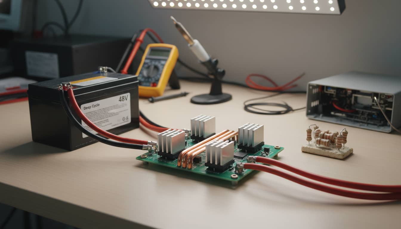
To build an inverter, we must first master the signal. We start with a stable DC voltage, Vdc, for example, 48V from a battery bank. Our goal is a pure sine wave, Vac, at 230V RMS.
The H-Bridge: The First Tool
The most primitive way to create AC from DC is the H-Bridge. Imagine four switches arranged like the letter ‘H’ with the load in the center. By closing the top-left and bottom-right switches, current flows forward through the load (representing a positive DC voltage, +Vdc). By flipping the switches—closing top-right and bottom-left—current flows backward (representing a negative DC voltage, -Vdc).
If we toggle these switches 50 times a second, we do not get a sine wave. We get a Square Wave. Mathematically, this is the most basic AC form. Its behavior is described by a formula where the function of the waveform over time, f(t), is determined by the signum function of a sine wave oscillating at a specific angular frequency over time. This results in an output that instantly switches between the positive and negative DC voltage values, creating the characteristic square shape.
While this provides alternating current, it is a “brutal” waveform for sensitive electronics. To understand why, we must look at it through the lens of Fourier Analysis.
The Fourier Series Expansion: The “Truth” of the Wave
Joseph Fourier taught us that any periodic waveform, no matter how sharp its edges, is mathematically constructed of a sum of sine waves. When we analyze our H-Bridge square wave, the Fourier expansion reveals a dirty secret.
The voltage of the square wave over time, represented as V_square(t), can be described as an infinite sum of sine waves. The formula is calculated as four times the DC voltage (4Vdc) divided by pi (π), multiplied by the summation of sine wave components. This summation starts from an index ‘n’ of 1 and includes only odd integer values (1, 3, 5, and so on) up to infinity. For each term in the sum, a sine wave is generated with a frequency that is an integer multiple ‘n’ of the fundamental angular frequency. The amplitude of each of these sine waves is scaled by the reciprocal of that integer ‘n’.
This equation tells a frightening story for an engineer:
- The Fundamental (where n=1): This is the 50Hz sine wave we want.
- The Harmonics (where n=3, 5, 7, etc.): These are the “pollution.” The square wave contains a 3rd harmonic (150Hz) at 1/3rd the amplitude, a 5th harmonic (250Hz) at 1/5th the amplitude, and so on, extending to infinity.
Spectral Domain Visualization:
Theoretically, if you viewed this on a spectrum analyzer, you would see a tall spike at 50Hz, followed by a menacing “comb” of spikes gradually decreasing in height. In a practical MEA setting, these harmonics are not just math—they are heat. If you feed this square wave into an AC motor (like a ceiling fan in Mumbai or a water pump in Sudan), that 3rd and 5th harmonic energy does not spin the motor; it is dissipated as waste heat in the windings, leading to premature failure in hot climates.
The Solution: PWM and Spectral Manipulation
We cannot mechanically filter the low-frequency harmonics (like 150Hz) easily; the inductor required would be the size of a watermelon, too expensive and heavy for modern logistics. The solution is signal processing: Pulse Width Modulation (PWM).
Instead of switching just once per cycle (50Hz), we switch thousands of times per second (e.g., 20kHz). We vary the width of the pulses. Wide pulses simulate the peak of the sine wave; narrow pulses simulate the zero-crossing.
From a signal processing perspective, PWM does something brilliant. It does not remove the harmonic energy; it shifts it. By switching at 20kHz, the first major harmonic cluster appears around 20kHz, leaving the spectrum between 50Hz and 20kHz relatively empty.
The LC Filter: The Final Gatekeeper
Now, we only need to remove the high-frequency switching noise. We use an LC Low-Pass Filter (Inductor and Capacitor). The transfer function of this filter, denoted as H(s), is calculated as 1 divided by the sum of three terms: the product of inductance (L), capacitance (C), and the square of the complex frequency (s^2); plus the product of resistance (R), capacitance (C), and the complex frequency (s); plus 1.
We tune the resonant frequency (cutoff) of this filter to roughly 1kHz–2kHz.
- At 50Hz: The filter acts like a transparent window (Gain is approximately 1). Our fundamental wave passes through.
- At 20kHz: The filter acts like a brick wall. The high-frequency switching noise created by PWM is attenuated by -40dB/decade or more.
The result: The jagged PWM pulses are smoothed into the beautiful, clean Pure Sine Wave required for modern civilization.
Part 2: Control Systems & PWM Strategy
The “Brain”: Managing Stability in an Unstable World
Having established the physics, we must discuss control. In an off-grid scenario, input conditions are rarely ideal. A battery under heavy load in a Nigerian evening might sag to 44V. A cloud passing over a solar array in Vietnam causes voltage fluctuation. Yet, the output must remain a locked 230V/50Hz.
The Closed-Loop System
An inverter is a classic closed-loop feedback system.
- Reference: A digital look-up table inside the microcontroller generates a perfect mathematical sine wave representation.
- Feedback: Sensors measure the actual output voltage and current.
- Error Signal: The controller compares the Reality (Output) vs. the Ideal (Reference).
- Action: A PID (Proportional-Integral-Derivative) controller adjusts the PWM width to correct errors instantly.
Sine-Triangle PWM (SPWM)
The standard method for generating the switching logic is SPWM. The microcontroller generates a high-frequency triangular “carrier” wave (e.g., 20kHz) and compares it against the low-frequency sinusoidal reference (50Hz).
- When Sine > Triangle: Switch High.
- When Sine < Triangle: Switch Low.
This naturally creates the variable pulse widths required. However, in modern high-end inverters, we use Space Vector Modulation (SVM). SVM treats the inverter states as vectors in a complex plane. While mathematically more intensive, SVM uses the DC bus voltage 15% more efficiently than SPWM—crucial for squeezing every watt out of a solar bank in a remote African mini-grid.
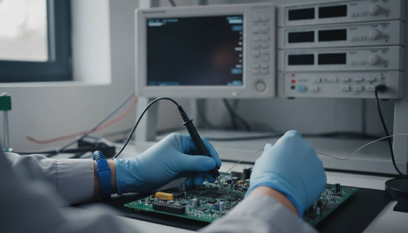
Part 3: Component-Level Hardware & Environmental Reliability
The “Brawn”: Surviving the Heat and Dust
The math is clean; the reality in MEA & SEA is dirty. A theoretical sine wave does not care about temperature, but a MOSFET does. This section details the hardware limitations imposed by our target regions.
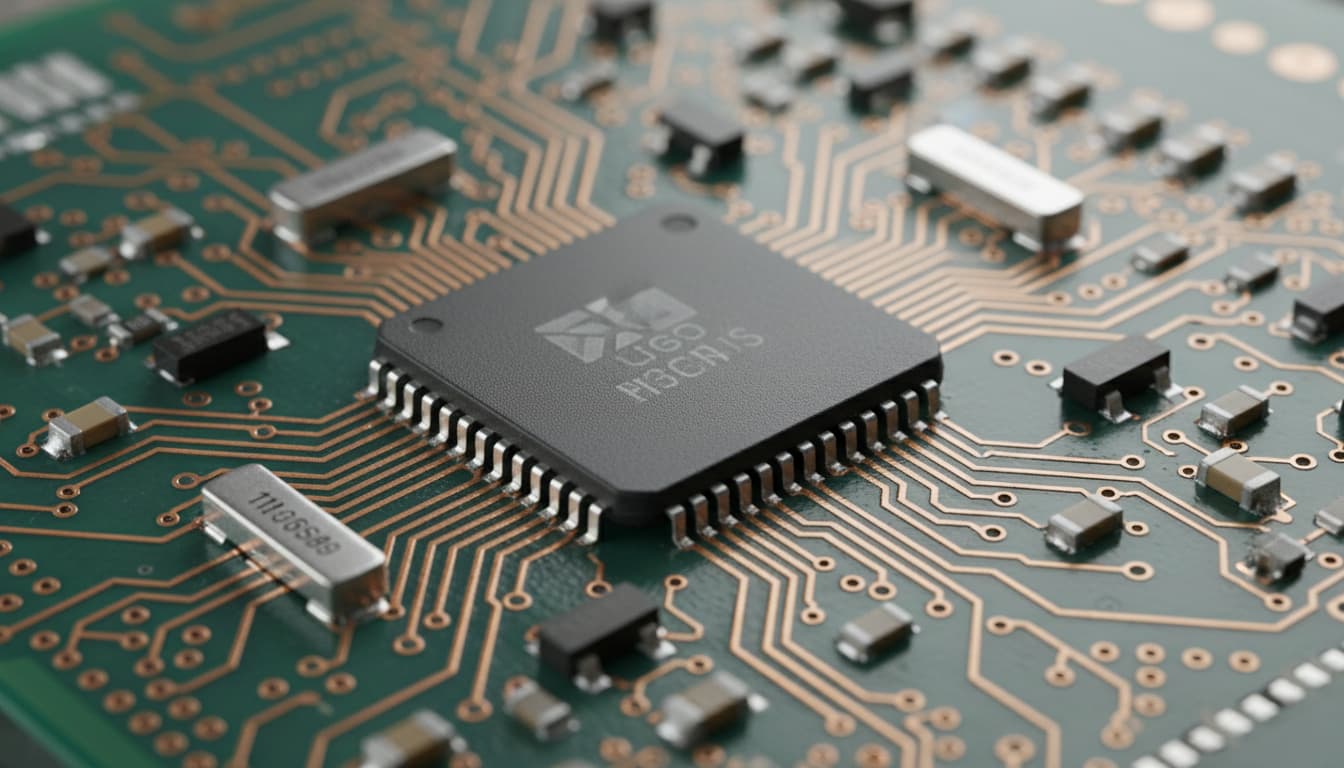
Power Switches: MOSFETs vs. IGBTs
The switches discussed in our H-Bridge are usually MOSFETs (for lower voltages, <100V) or IGBTs (for higher voltages, >600V).
In the Middle East, ambient temperatures often reach 50°C. Inside an inverter enclosure, this can rise to 70°C or 80°C.
- Thermal Runaway: As Silicon MOSFETs heat up, their internal resistance, denoted as R_DS(on), increases. Higher resistance means more heat generation, calculated as the square of the current (I) multiplied by the resistance (R), which in turn causes more resistance. This is a death spiral.
- Engineering Solution: Inverters designed for Germany will fail here. For MEA markets, we must derate. A 5kW inverter might use components rated for 10kW to ensure they stay within the Safe Operating Area (SOA) despite the heat.
The LC Filter Components: Real-World Failure Points
- The Inductor (L): Saturation/Heat The inductor stores energy in a magnetic field. In high-heat environments (like a metal container in the Sahel), the ferrite or iron-powder core can approach its Curie Temperature, losing magnetic properties. If the core saturates, the inductor stops being an inductor and becomes a short circuit. The result? Instant switch destruction. High-quality inverters use high-flux cores specifically chosen for high-temp stability.
- The Capacitor (C): The Achilles Heel The capacitor smooths the output. The most common type is the Aluminum Electrolytic. Ideally, it contains a liquid electrolyte.
- The Problem: In hot climates, this electrolyte evaporates over time. Arrhenius’s Law states that for every 10°C rise in temperature, the capacitor’s life is halved. A cheap capacitor rated for 2000 hours at 85°C might last 5 years in Hamburg but only 18 months in a localized shed in Jakarta.
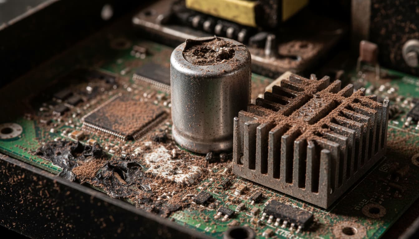
* **The Solution:** Premium inverters for these regions use Film Capacitors or high-grade 105°C rated electrolytic capacitors to ensure longevity.Protection: Humidity and Dust
- SEA (Southeast Asia): High humidity leads to condensation on the PCB. This causes dendritic growth and short circuits. Manufacturers must use Conformal Coating (a chemical spray) to seal the circuit board.
- MEA (Middle East/Africa): Dust is conductive and insulative. It coats heatsinks, preventing cooling, and can bridge electrical contacts. IP65 Enclosures (sealed against dust and water jets) are not a luxury here; they are a necessity for reliability.
Part 4: Market Landscape & Application Case Studies
Commercial Context: Solutions for Specific Needs
Understanding the inverter requires understanding who buys them and why. The MEA & SEA markets are bifurcated between “Price” and “Reliability.”
The Competitive Landscape
- Global Premium (e.g., Victron, SMA, Schneider): Dominant in critical infrastructure, NGOs, and high-end residential. They offer field-serviceable parts and extreme weather ratings.
- Chinese Volume Leaders (e.g., Growatt, Goodwe, Deye): These players have revolutionized the market by offering “Good Enough” quality at aggressive price points. They are the engine of residential adoption in Vietnam and South Africa.
- Local/Regional Assembly: India and Turkey perform some assembly, but the core IP usually resides in China or Europe.
Application Case Studies
Case Study 1: Rural Electrification (Sub-Saharan Africa)
- Context: A typical specialized Solar Home System (SHS) in rural Kenya.
- Load: LED lights, phone charging, a small TV.
- Inverter Requirement: Highly efficient at low loads. A cheap inverter might burn 25W just to stay “on” (self-consumption). If the solar battery is small, this idle loss destroys the system’s economic viability. The push here is for “All-in-One” units (Inverter + Solar Charger) that are robust and simple.
Case Study 2: Telecom Towers (Southeast Asia)
- Context: Islands in the Philippines or Indonesia. Towers run 24/7.
- System: Hybrid (Solar + Lithium Battery + Diesel Gen-set backup).
- Inverter Requirement: The inverter acts as the grid manager. It must start the diesel generator automatically via a dry-contact relay when the battery is low. Reliability is paramount; a technician trip involves a boat ride and costs hundreds of dollars.
Case Study 3: The Urban “Grid-Interactive” (Middle East/South Africa)
- Context: Dealing with “Load Shedding” in Johannesburg or Beirut.
- Load: High inrush currents (Air Conditioners).
- Requirement: Surge capability. When an AC compressor kicks in, it draws 5-7x its rated operational current for a split second. The inverter’s transformer and MOSFETs must handle this surge without tripping the overload protection.
Part 5: Economic Viability & Regional Policy Impact
The Bottom Line: TCO and The Cost of Reliability
Finally, we analyze the economics. In developing markets, the “Initial Sticker Price” often dictates the purchase. This is a trap.
Total Cost of Ownership (TCO)
As engineers, we must communicate TCO to financiers.
- Efficiency Math: An 85% efficient square wave inverter vs. a 95% efficient pure sine wave inverter.
- If you need 5kWh of daily energy, the 85% inverter requires you to generate 5.9kWh. The 95% inverter requires 5.2kWh.
- The “Cheap” inverter forces you to buy 15% more solar panels and 15% more battery capacity. The “System Cost” is actually higher with the cheap inverter.
- Appliance Damage: Running a fridge on a modified sine wave causes the motor to run hotter and approximately 20% less efficiently. This shortens the fridge’s life and increases energy demand.
Policy and Financing
- PAYG (Pay-As-You-Go): In Africa, companies like M-KOPA allow users to pay for solar systems daily via mobile money. This business model requires the hardware to last 3-5 years to recoup the investment. If the inverter burns out in year 1 due to heat, the customer stops paying, and the asset becomes a loss. High-quality inverters are the collateral of the PAYG industry.
- Standards: Programs like Lighting Global (Verasol) test and certify these inverters. Countries in East Africa are increasingly adopting these standards to stop the dumping of e-waste (sub-standard inverters) into their markets.
Conclusion
The journey of the inverter is a journey of transformation. We take the raw, static potential of chemistry (DC Battery) and sculpt it through violent switching and elegant filtering into the smooth, rhythmic heartbeat of the grid (AC Sine Wave).
For the engineer in the Middle East, Africa, or Southeast Asia, this is not just an academic exercise. It is a battle against thermodynamics, dust, and economic scarcity. By understanding these first principles—from the Fourier series to the thermal limit of a capacitor—we can design and select systems that do not just work in a lab, but provide light, connectivity, and opportunity in the toughest environments on Earth.