Overview of Hybrid PV-Storage Systems
Hybrid PV-storage systems combine photovoltaic (PV) panels, batteries, and one or more inverters to supply a household with renewable energy, manage grid interactions, and provide backup power. In the Middle East, Africa, and Southeast Asia (MEA & SEA), factors like extreme heat, dust, high humidity, and unreliable grid power shape system design. Key goals include reliable daytime solar self-consumption and nighttime or outages supply, while respecting local codes and standards. Matching batteries and inverters correctly is crucial for safety, performance, and cost-effectiveness. The core of our analysis is a Weighted Decision Matrix that scores candidate configurations against technical criteria such as voltage compatibility, power ratings, efficiency, safety, and cost to guide the optimal choice for a given application.
System Architectures: AC- vs DC-Coupling
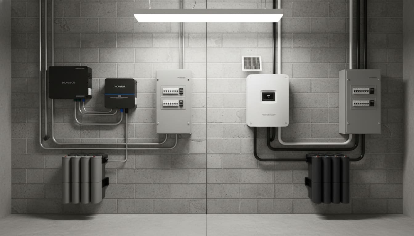
PV and battery systems can be connected in different ways. The two primary architectures are AC-coupled, where the PV and battery each feed the AC side of the system, and DC-coupled (hybrid), where the PV and battery share a DC bus before inversion to AC. Their characteristics differ as follows.
| Characteristic | AC-Coupled (Separate Inverters) | DC-Coupled/Hybrid (Integrated) |
|---|---|---|
| Configuration | PV panels power a solar inverter; battery charges via an AC–DC charge controller. Each has a separate converter. | PV panels and battery connect on a common DC bus; a hybrid inverter manages both and outputs AC. |
| Efficiency (battery charge) | ~90–92% (AC charging losses) | ~96–99% (direct DC charging) |
| Power Flow | PV → DC→AC→loads; battery AC→DC→AC→loads (extra conversion) | PV→battery DC→AC→loads (direct charging, fewer conversions) |
| Scalability | Easy to expand PV capacity (higher voltages, multiple MPPTs); adding batteries requires compatible inverter-chargers. | Hybrid inverter limits panel voltage range; adding PV modules must fit inverter MPPT specs. |
| Grid Interaction / Backup | Suits retrofits and multi-inverter grids; PV can island through a grid-forming inverter. | Inverter controls islands directly; generally needs one point of control (backup-generator interface). |
| Complexity & Cost | Can be more complex (extra inverters, wiring); moderate cost. | Typically simpler wiring; a hybrid inverter can be more expensive per kW but saves components. |
| Typical Use Cases | High-power systems (>6 kW), retrofits on existing PV systems, or when maximum solar capture is needed. | New installs, small-medium homes (3–10 kW); where space or cost constraints favor one unit. |
In summary, DC-coupled hybrid inverters tend to be more efficient at charging the battery (up to 99%) than AC-coupled systems, but AC-coupled architectures offer flexibility, which is useful for off-grid microgrids or retrofits. For a household system in MEA/SEA, a hybrid inverter is common due to high solar insolation and a desire for simplicity, unless an existing PV array is present, in which case AC-coupling might be chosen. Further details on how off-grid homes often prefer AC-coupled flexibility and how DC-coupling is usually favored for efficiency in electricity bill optimization are available in their respective guides.
Voltage Compatibility and Battery Sizing
Battery Nominal Voltage: Batteries come in standardized voltages such as 48 V, 100 V, and 400 V. Household hybrid inverters commonly use 48 V DC batteries for systems around 5–10 kWh. Ensure the battery’s nominal voltage matches the inverter’s DC-bus rating. For example, many single-phase home inverters are designed around a 48 V battery stack, often with three 16 V strings in series. Higher voltage battery systems (400+ V) are more typical in large commercial setups.
PV Array Voltage (MPPT Range): The solar PV array must produce a DC voltage within the inverter’s Maximum Power Point Tracking (MPPT) window. For example, a hybrid inverter might accept 200–450 V from the panels. The PV open-circuit and nominal voltages should be sized so that the voltage stays in range during typical operating temperatures. In hotter climates, such as the Middle East under the noon sun, panel voltage drops, so the array configuration must consider the worst-case ambient temperature to avoid under-voltage.
Capacity and Connection: If using a 48 V hybrid inverter, use a 48 V nominal battery bank. For multi-phase homes with a three-phase grid, sometimes three identical 48 V inverters are installed. The battery’s capacity (Ah or kWh) should be chosen to meet energy needs, and you must ensure that the inverter’s continuous DC charging and discharging currents (in amps) do not exceed battery specifications. For instance, a 5 kW inverter at 48 V implies a direct current of about 104 amps, as calculated by dividing the power (5000 watts) by the voltage (48 volts). Consequently, batteries and cabling must be sized accordingly.
Power Ratings: Continuous and Peak
Continuous vs. Peak Power: Inverters specify both continuous output power and short-term peak or surge capacity. For instance, a 5 kW hybrid inverter might support a 10 kW surge for 5 seconds to handle motor starts. Batteries also have continuous discharge ratings, often tied to their C-rate. Ensure the continuous discharge current (A) and inverter power are well-matched. A mismatch, such as a small battery paired with a large inverter, can overload either the battery or the inverter.
Load Matching: Estimate household loads, including air conditioners, pumps, and appliances, and ensure the inverter can sustain these loads. For UPS/Backup design, oversizing the inverter relative to the expected load peak ensures reliability during outage surges. Likewise, ensure the PV array size doesn’t vastly exceed the inverter’s PV input capacity. A rule-of-thumb allows for up to 150% DC/AC oversizing, but always check the inverter’s specification.
System Responsiveness: During outages or brownouts, which are common in parts of Africa and SEA, the inverter’s ability to switch to battery power rapidly (often less than 20 ms for grid-forming inverters) is critical. Hybrid inverters typically have an “anti-blackout” or UPS mode specification. Confirm the inverter is rated for backup operation, often labeled as “EPS” or “EPS mode” in manufacturer specs, as not all grid-interactive inverters support unassisted off-grid use.
Side-by-Side Technical Comparison
Rather than a purely textual comparison, we summarize key specs for typical battery and inverter types in the tables below.
Table 1: Comparison of Battery Technologies (LFP vs. NMC)
| Parameter | LFP (LiFePO₄) | NMC (LiNiMnCoO₂) |
|---|---|---|
| Nominal Voltage | ~3.2 V per cell (arrays often 48 V) | ~3.7 V per cell (48 V safer designs) |
| Energy Density | ~90–160 Wh/kg (lower) | ~150–250 Wh/kg (higher) |
| Cycle Life (to 80% DoD) | ~3,000–6,000 cycles (8–13 years) | ~1,000–2,000 cycles (3–5 years) |
| Depth of Discharge | 100% usable (practically) | Often limited to ~80% for longevity |
| Calendar Life | >10 years (very stable chemistry) | ~5–10 years (varies, sensitive to stress) |
| Cost per kWh (approx.) | Lower (e.g., 100–150 USD/kWh) | Higher (e.g., 150–200 USD/kWh) |
| Safety (thermal stability) | Very high (non-volatile cathode, safer in fire test) | Lower (can burn vigorously if misused) |
| Temperature Tolerance | Operates up to ~60°C; poor below -20°C (requires heating) | Similar range but more sensitive at high temperatures |
| Self-heating Risk | Very low; robust against thermal runaway | Higher (oxygen release can feed fire) |
| Recycling/Environmental | Iron and phosphate are abundant/non-toxic | Cobalt is toxic/expensive, with supply-chain risk |
| Comments | Preferred for stationary storage due to safety and lifecycle. | Higher energy density, but more costly and shorter-lived. |
Table 2: Example Inverter Topologies for Home PV-Storage
| Feature / Spec | AC-Coupled Inverter (String Inverter) | Hybrid DC-Coupled Inverter |
|---|---|---|
| Function | Converts PV DC→AC; grid-tie only | Converts DC↔AC; manages battery charging |
| Battery Connection | None (battery via separate inverter/charger module) | Direct (battery plugs into inverter’s DC port) |
| DC Voltage Range | Typically 200–1000 V (high-voltage strings) | Often low-voltage (e.g., 48 V battery) + PV MPPT range (e.g., 200–450 V) |
| Power Rating | E.g., 5 kW (continuous PV→grid) | E.g., 5 kW (continuous AC output), ~100 A DC charging |
| Efficiency | PV→grid ~97%; battery charge via AC ~90–92% | PV/battery DC efficiency ~96–99% |
| Phase | Single or Three-phase (use appropriate model) | Same options; pick phase matching the house. |
| Grid-Forming Capability | Usually not (relies on grid for reference) | Many support off-grid/UPS mode (check specs) |
| Certifications | IEC 62109 for safety (ground-fault, etc.) | IEC 62109-1/3 plus relevant battery tests |
| Use-case | Add-on PV to an existing system | New combined PV+storage installations |
These tables illustrate that LFP batteries tend to score higher on safety and lifetime (longer cycle life, greater thermal stability) at the expense of lower energy density, while hybrid inverters simplify the system layout and achieve higher charging efficiency. Such side-by-side comparisons help the decision matrix process.
Weighted Decision Matrix: Matching Components
To choose the best battery-inverter pairing or architecture, we define criteria and assign relative weights that reflect system priorities. The matrix scores options on each criterion and computes weighted totals. Below is a sample decision matrix comparing two options for a generic household system:
- Option A: Hybrid inverter with LFP battery
- Option B: Hybrid inverter with NMC battery
| Selection Criteria | Weight | Option A (LFP) | Weighted | Option B (NMC) | Weighted |
|---|---|---|---|---|---|
| Voltage Compatibility | 20% | 9 (exact match) | 1.8 | 9 (same inverter) | 1.8 |
| Continuous Power Match | 10% | 8 (well sized) | 0.8 | 8 | 0.8 |
| Charging Efficiency | 10% | 9 (LFP has slight efficiency edge) | 0.9 | 8 | 0.8 |
| Round-Trip Efficiency | 10% | 9 (LFP is marginally better at high DoD) | 0.9 | 8 | 0.8 |
| Cost (Initial) | 15% | 8 (cheaper per kWh) | 1.2 | 6 (higher cost) | 0.9 |
| Cycle Life (Lifetime) | 15% | 9 (8–13 years) | 1.35 | 6 (3–5 years) | 0.9 |
| Safety & Certifications | 15% | 9 (very stable chemistry) | 1.35 | 6 (flammability risk) | 0.9 |
| Environmental Tolerance | 5% | 8 (tolerates heat well) | 0.4 | 7 (somewhat lower stability) | 0.35 |
| Total Score | 100% | 8.8 | 6.8 |
Scores are rated on a scale from 1 to 10. The weighted score is calculated by dividing the option’s score by 10 and then multiplying the result by the criterion’s weight.
In this example, Option A (LFP) achieves a higher total score (8.8 vs. 6.8), mainly because of its greater longevity and safety. The weights emphasize factors important for a typical residential backup and storage system: compatibility, total lifetime, and cost. If priorities change, such as maximizing energy density or initial power, the weights and scores would be adjusted. Always tune the weights for the specific scenario; for example, cost-sensitive users might assign a higher weight to cost, whereas high-reliability applications like a UPS would weigh safety and cycle life more heavily.
LFP’s higher cycle count and stability mean fewer replacements, lowering the total cost of ownership (TCO) in the long run. These intuitions are formalized in the table above. For each use-case or scenario, a similar matrix is used with scenario-appropriate weights.
Total Cost of Ownership (TCO) Analysis: LFP vs. NMC Example
To quantify the economic trade-offs between LFP and NMC batteries in a household PV-storage system, we model a 3–4 bedroom home in Thailand, which has a typical consumption of approximately 12 kWh per day. We assume:
- Daily energy storage required: 6 kWh, to shift the solar peak to the evening and cover partial night usage.
- Battery usable capacity: 8 kWh, accounting for the usable depth of discharge.
- Round-trip efficiency: Approximately 95% for LFP and 90% for NMC.
- Battery Costs: An LFP pack at $120/kWh and an NMC pack at $150/kWh, based on phased, system-level prices.
- Cycle life to 80%: LFP offers approximately 3,000 cycles (about 10 years at 0.8 DoD), while NMC provides about 1,500 cycles (roughly 5 years).
- Electricity tariff: $0.15/kWh, which is the approximate residential rate in Thailand.
Calculation: We compare the net cost over 10 years. The LFP battery requires only the initial purchase, whereas the NMC battery needs approximately two replacement packs over the 10-year period due to its 5-year life. Assuming a labor installation cost of $100 per replacement and ignoring smaller operation and maintenance differences, the comparison is as follows:
| Cost Component | LFP (8 kWh) | NMC (8 kWh) |
|---|---|---|
| Initial battery cost | 8 kWh multiplied by $120 equals $960 | 8 kWh multiplied by $150 equals $1,200 |
| Replacements (10 yr) | None (still >80% capacity after 10 years) | Two replacements at $1,200 each plus two installations at $100 each equals $2,600 |
| Total battery cost | $960 | $3,800 |
| Electricity saved (10 yr) | Approximately 6 kWh/day multiplied by 365 days by 10 years, multiplied by $0.15, results in about $3,285 | Same potential saving of approximately $3,285 |
| Net Battery TCO | A capital expenditure of $960 minus $3,285 in savings equals a net saving of –$2,325 | A total cost of $3,800 minus $3,285 in savings equals a net cost of $515 |
Over 10 years, the LFP battery system appears to pay for itself, resulting in a net saving of $2,325. In contrast, the NMC system requires an extra investment of $515 due to replacements. The effective levelized cost per stored kWh over 10 years, ignoring the inverter and other components, would be approximately $0.04/kWh for LFP versus about $0.08/kWh for NMC.
A sensitivity analysis shows that even with a 20% change in the electricity tariff, LFP maintains a lower TCO. If the tariff drops to $0.12/kWh, the 10-year savings decrease to about $2,628; LFP TCO is still negative (–$1,668), while NMC’s net cost rises to +$860. If the tariff rises to $0.18/kWh, savings increase to approximately $3,942; LFP’s net becomes –$2,982, and NMC’s becomes +$142. In all scenarios, LFP’s lifetime advantage yields a lower TCO. These are rough figures assuming constant usage and prices; actual outcomes will vary with usage patterns, financing, and exact component costs.
This model assumes battery cost only; the inverter, installation, and any subsidized finance costs can alter the results. However, the much higher cumulative cost of replacing NMC batteries is a robust outcome. In practice, local incentives such as subsidies, tariffs, and financing, along with specific usage patterns, should be used to refine the calculation.
Environmental and Regional Considerations
High Ambient Temperatures (Middle East)
Components must tolerate temperatures up to 50°C or more. LFP chemistry degrades less than NMC at high temperatures, which can accelerate battery aging. Provide shading or ventilation for batteries and inverters if needed. Use battery specifications with a wide operating range. Inverters should have cooling systems like fans or heat sinks and be rated for high-heat climates, with operational capabilities up to 60°C.
Grid Instability (Africa)
Frequent outages and voltage spikes demand high reliability. Use inverters or inverter-chargers with built-in UPS features and surge protection. Batteries should support deep discharge to ride through long outages. The decision matrix should assign a heavier weight to lifetime and robustness, as in the Backup Power scenario. Fuse protection and compliance with local wiring rules are critical.
High Humidity & Corrosion (SEA)
Tropical humidity and rain require IP65-rated enclosures or indoor installation in ventilated, dehumidified spaces.
Any outdoor components, such as junction boxes and panel wiring, must be corrosion-resistant. Batteries and inverters should possess anti-condensation features if installed in coastal or humid areas. Incorporate moisture barriers and ensure electronics have conformal coatings when possible.
Dust and Sand
In desert regions like the Middle East and Africa, dust ingress can clog cooling fins. It is advisable to use units equipped with dust filters or to establish routine maintenance plans. Additionally, position air intakes away from direct sand flows.
These regional factors should alter the decision weights in the selection matrix. For instance, in the Middle East, place extra weight on battery temperature tolerance. In Africa, prioritize system reliability and surge immunity. In Southeast Asia, focus on humidity protection. The quick-start tables in Part B explicitly annotate such adjustments.
8. Standards, Safety, and Certifications
International Standards
Ensuring safety and compliance is paramount. The main standards include IEC 62109 for the safety of PV inverters and IEC 62619 for the safety of stationary batteries. Adherence to these standards means both the inverter and the battery must pass rigorous abuse tests, which ensures that risks such as over-voltage, short-circuits, ground faults, and thermal runaway are mitigated.
Third-Party Certification
Certification by recognized labs like TÜV SÜD, UL, and CSA provides an additional layer of trust. A TÜV- or UL-listed battery has been tested against standards such as UL 1973 for stationary battery safety or UL 9540A for fire energy storage systems. Similarly, inverters should have IEC 62109 or UL 1741 compliance. Products bearing these marks, along with the CE mark for EU and Middle East markets, are more likely to be safe and insurable.
Why Certifications Matter
A certified battery has undergone rigorous tests for short-circuits, overcharging, and thermal abuse. Even if only the individual battery cells are IEC 62619 certified, the complete battery pack or system should ideally be UL 1973 or UL 9540 certified. Likewise, certified inverters have engineered protections against faults and islanding, which is a key safety feature covered by standards like UL 1741 and IEC 62109.
Integration Safety (IEC 62933)
Component certification alone is not enough; proper system integration is critical. When matching a battery type with an inverter, ensure the manufacturer provides a compatible configuration, as many systems require a specific firmware setting for the battery type. Incorrect settings, such as applying an NMC battery profile to LFP cells, can lead to unsafe operation despite individual component certifications.
By selecting certified products and following IEC and UL guidelines, installers can ensure warranty compliance and user safety. Always verify the certification labels on each unit and request documentation from suppliers.
Part B: Scenario-Based Quick Start Guides
For each of the three common household goals, we provide a tailored checklist and a simplified pre-weighted decision matrix. The matrices emphasize criteria critical to the scenario but link back to the detailed discussion in Part A for rationale. Environmental adaptations for heat, humidity, and grid stability are noted in each case.
1. UPS/Backup Power Focus
Scenario
The priority is reliable backup during grid outages. The home may experience long blackouts, which are common in parts of Africa and Southeast Asia, and needs to support critical loads such as lighting, refrigeration, and communication devices. A rapid transition to battery power is essential.

Checklist
- Generator-Style Inverter: Choose a hybrid inverter with fast switching or an Emergency Power Supply (EPS) mode. Verify its “UPS” or backup mode specification.
- Battery with High Depth-of-Discharge: Use a battery chemistry that allows deep discharge. LFP is well-suited for full Depth of Discharge (DoD), whereas NMC is usually limited to approximately 80%.
- High Cycle Life: Prioritize a long-lived battery, such as LFP which typically offers over 3000 cycles, so that frequent outages do not necessitate premature replacements.
- Capacity for Overnight Backup: Size the battery for hours of reserve power at minimum loads. For example, a 10 kWh usable battery bank for a 5 kW load.
- Surge Capacity: Ensure the inverter’s peak power, which should be at least double its continuous rating, can cover the startup surges of AC loads like motors and pumps.
- UV/Surge Protection: Add surge protectors for lightning and reflected surges, as grid voltage swings are common.
- Cooling and Ventilation: In hot climates, the inverter and Battery Management System (BMS) require adequate cooling to sustain prolonged output. Install them in a shaded, well-ventilated room.
- Redundancy: If possible, use multiple parallel inverters or batteries for critical backup. If one unit fails, the backup system will still function.
- Certification: All equipment, including the battery pack and inverter, should be UL or TUV certified for off-grid use, as per the recommendations in section 8.
For more on compatibility, see Part A: Sections 3–4. For grid-independence design, see Off-Grid Focus in Part B.
Pre-Weighted Decision Matrix (Backup Focus)
| Criteria | Weight | LFP Battery + Hybrid Inverter | Weighted | NMC Battery + Hybrid Inverter | Weighted |
|---|---|---|---|---|---|
| Battery Depth-of-Discharge | 25% | 10 (full usable) | 2.5 | 8 (often curtailed to 80%) | 2.0 |
| Cycle Life (Lifetime) | 25% | 10 (highest durability) | 2.5 | 6 (shorter life) | 1.5 |
| Continuous Discharge Rating | 15% | 9 (matches high loads) | 1.35 | 8 | 1.2 |
| Safety (Thermal Stability) | 15% | 10 (very stable chemistry) | 1.5 | 6 (higher fire risk) | 0.9 |
| Initial Cost | 10% | 7 (mid-range) | 0.7 | 5 (more expensive) | 0.5 |
| Temperature Tolerance | 10% | 8 (good high-temp) | 0.8 | 7 (less robust above 45°C) | 0.7 |
| Total Score | 100% | 9.35 | 6.8 |
Choosing the Best Fit: The matrix clearly favors LFP-based systems for UPS use, with a score of 9.35 versus 6.80, due to their deeper discharge capability and longer life. In a backup scenario, maximizing runtime and cycle durability is paramount and outweighs the initial cost. Always verify that the chosen hybrid inverter supports “islanding” and UPS mode, as some grid-tied models lack this functionality.
2. Electricity Bill Optimization Focus
Scenario
The goal is to minimize grid electricity bills by maximizing self-consumption of solar energy and arbitraging time-of-use tariffs. Outages are short or infrequent, and the household may have predictable peak tariff hours.
Checklist
- High Efficiency Setup: Choose a DC-coupled hybrid inverter to minimize conversion losses.
- Battery with High Round-Trip Efficiency: LFP often yields slightly better efficiency; ensure BMS losses are low.
- Maximize Depth of Discharge: To use as much stored solar energy during peak times, favor LFP chemistry, which supports 100% DoD.
- Optimize Battery Size vs. PV: Size the battery to store excess midday PV generation for evening use.
- Time-of-Use Awareness: If tariffs vary, program the inverter to charge during off-peak hours (if grid charging is allowed) and discharge during peak hours.
- MPPT Sizing: Configure the PV array so that the panels can supply both the load and charge the battery. For instance, allow for slight oversizing of the PV array relative to the battery capacity.
- Lower-Cost Options: If the budget is tight, AC-coupled systems with existing inverters can be a viable option, but be prepared to accept slightly lower efficiency.
- Regulatory Compliance: Check if local regulations allow selling excess power back to the grid. If so, ensure the inverter has export settings.
- Certifications: Verify that the components have official certifications to avoid resale issues with utility companies, as detailed in Part A, Section 8.
For detailed matching, see Part A: Voltage Compatibility and TCO analysis.
Pre-Weighted Decision Matrix (Bill Optimization)
| Criteria | Weight | LFP Battery + Hybrid Inverter | Weighted | AC-Coupled Inverter + NMC Battery | Weighted |
|---|---|---|---|---|---|
| Round-Trip Efficiency | 25% | 10 (max efficiency) | 2.5 | 8 (slightly lower) | 2.0 |
| Depth of Discharge | 20% | 10 (full use) | 2.0 | 8 (limited use) | 1.6 |
| Battery Cost per kWh | 15% | 8 (moderate) | 1.2 | 6 (higher) | 0.9 |
| Battery Life | 15% | 9 (long-lived) | 1.35 | 6 (short life) | 0.9 |
| Ease of Retrofit | 10% | 6 (new system required) | 0.6 | 9 (can add to existing PV) | 0.9 |
| Time-of-Use Flexibility | 15% | 9 (programmable) | 1.35 | 7 (supported by some systems) | 1.05 |
| Total Score | 100% | 9.00 | 7.35 |
Here, the LFP and hybrid inverter combination scores the highest (9.00). Efficiency and the full use of capacity are weighted most heavily, since every extra kWh stored saves money. The AC-coupled/NMC option lags due to lower round-trip efficiency and usable capacity. Retrofit ease was given some weight for cases with existing PV, but not enough to overcome the efficiency losses. Note that tariffs affect monetary savings: if the price differential between peak and off-peak is high, the weighting on efficiency and depth-of-discharge would be even higher.
3. Off-Grid Independence Focus
Scenario
The household is not reliably connected to any grid, or at most has a weak connection. The system must provide all energy needs from the sun (plus a generator); reliability and autonomy are key. Extreme environments, such as a remote Middle Eastern desert or a Southeast Asian village, often apply, bringing challenges like heat, dust, and humidity.

Checklist
- Robust Powertrain: Using an AC-coupled microgrid approach can allow for multiple inverters, facilitating expansion. However, a DC-coupled hybrid inverter is still common for its simplicity. Whichever is chosen, ensure grid-forming capability (off-grid mode) is specified.
- Large Storage Capacity: Size the battery high enough for several days of autonomy. Prioritize the battery’s usable capacity and cycle life; LFP is favored.
- Load Management: Implement critical versus non-critical circuit paneling, with critical circuits connected to the UPS circuits of the inverter.
- Environmental Hardening: Use components with high ingress protection (IP65) for outdoor inverters, desiccant breathers on battery enclosures, and elevated placement to avoid flooding.
- Thermal Management: In hot climates, use thermally stable batteries like LFP and possibly active cooling. In high-altitude winters, consider battery heating, especially for lead-acid or LFP batteries below -10°C.
- Blending Sources: If a generator is present, ensure the inverter can accept generator input or that an AC transfer switch is provided.
- Maintenance Plan: Design for easy maintenance, for example, by preferring modular batteries or drop-in replacements. Document expected battery lifetimes; LFP’s long life means less frequent replacements.
- Certifications & Local Codes: Check local electrification standards. In Africa, some regions require standards similar to IEC 61427 for off-grid battery systems. Use globally certified components to ensure safety.
See the Architecture and Environmental sections in Part A for more on system design in harsh conditions.
Pre-Weighted Decision Matrix (Off-Grid Focus)
| Criteria | Weight | LFP Battery + Hybrid Inverter | Weighted | Lead-Acid Battery + Commercial Inverter | Weighted |
|---|---|---|---|---|---|
| Cycle Life / Reliability | 25% | 10 (high) | 2.5 | 5 (low, ~500 cycles) | 1.25 |
| Depth of Discharge | 20% | 10 (full DoD) | 2.0 | 6 (typically 50% recommended) | 1.2 |
| Ruggedness (temp/humidity) | 15% | 8 (good heat tolerance) | 1.2 | 7 (sensitive to heat; watering needed) | 1.05 |
| Maintenance Requirement | 15% | 9 (low maintenance) | 1.35 | 4 (water top-ups, equalization) | 0.6 |
| Initial Cost | 10% | 6 (higher cost) | 0.6 | 8 (cheapest upfront) | 0.8 |
| Usable Energy (Efficiency) | 15% | 9 (high efficiency) | 1.35 | 5 (lower with inverter and DoD) | 0.75 |
| Total Score | 100% | 9.00 | 5.65 |
In remote or off-grid use, LFP batteries clearly lead over traditional flooded or sealed lead-acid batteries (9.00 vs 5.65). The matrix heavily rewards longevity and low maintenance, as off-grid sites often have limited maintenance capabilities, making batteries that last 10+ years indoors preferable. Lead-acid’s cheap initial cost is outweighed by its frequent replacement needs and capacity loss in heat. The Inverter column could similarly compare low-quality versus high-quality brand inverters, but here the critical decision was battery chemistry.
For architecture, off-grid systems may tolerate AC-coupled string inverters due to modularity and easier expansion, but hybrid inverters simplify DC-coupling. This table assumes a hybrid inverter is used; an AC-coupled alternative would score lower on efficiency. For humidity, ensure combiner boxes are Gland-sealed, and for extreme heat, use soil or air-cooled battery enclosures.
Scenario Note (Environment): In the Middle East desert, oversize the cooling systems (fans or evaporative cooling) for batteries and inverters. In tropical Southeast Asia, use waterproof enclosures and silica gel breathers. This “ruggedness” criterion was flagged in the matrix weighting.
Each of these scenario matrices is a simplified view; in real projects, many more nuances exist. However, by following the weighted criteria approach—tailoring weights to the objective and region—installers and DIY users can quickly identify the most suitable battery and inverter pairing. For deeper technical guidance on any matching issue, such as how to calculate cable sizes or MPPT voltage windows, refer back to the Core Technical Whitepaper (Part A) sections.